
Pulp Fiction, 1956 · page 80 of 162
Authentic Science Fiction Monthly, No. 65 — page 80: what you’re looking at
A restored page from Pulp Fiction, 1956. Page through the whole issue in the reader above.
📄 Transcribed text from this page (OCR, searchable)
Machine-transcribed from the original scan — historical spelling and the odd misread are preserved.
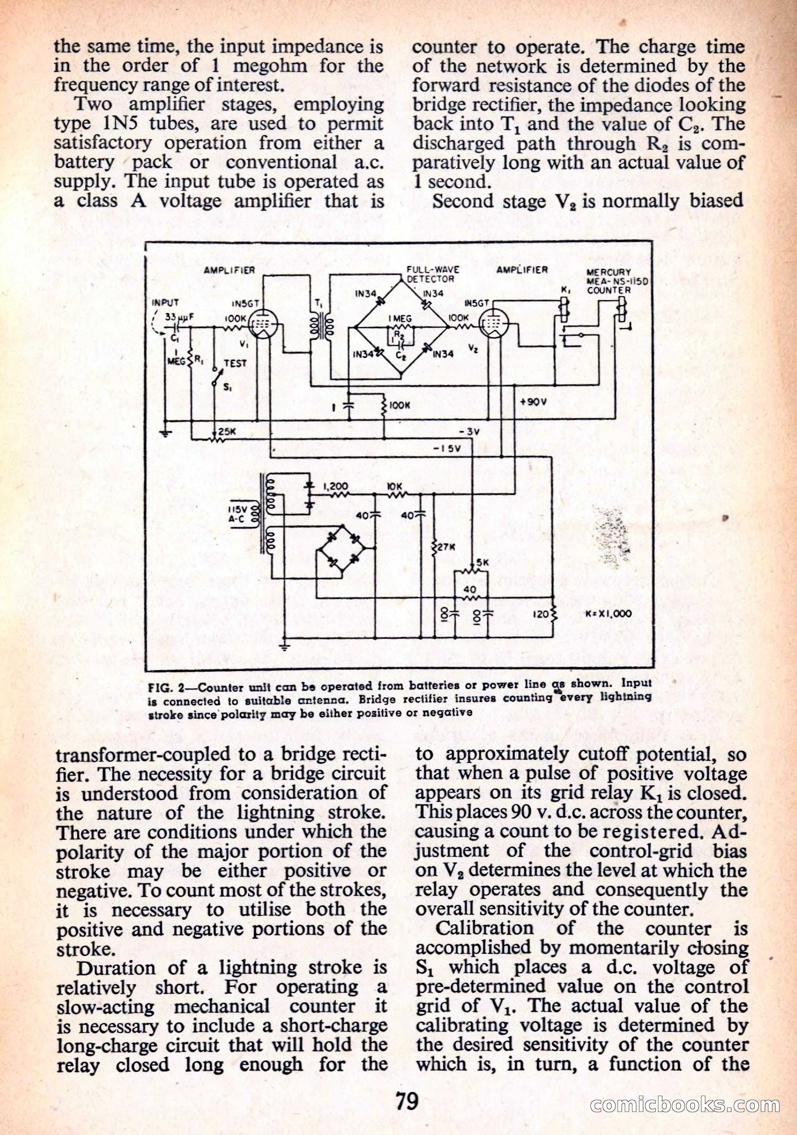
the same time, the input impedance is in the order of 1 megohm for the frequency range of interest. Two amplifier stages, employing type 1N5 tubes, are used to permit satisfactory operation from either a battery pack or conventional a.c. supply. The input tube is operated as a class A voltage amplifier that is AMPLIFIER & counter to operate. The charge time — E of the network is determined by the forward resistance of the diodes of the bridge rectifier, the impedance looking back into T, and the value of C,. The discharged path through R, is com- paratively long with an actual value of 1 second. Second stage V;, is normally biased FULL-WAVE AMPLIFIER FIG. 2—Counter unit can be operated from batteries or power line gs shown. Input is connected to suitable antenna. Bridge rectifier insures counting every lightning stroke since polarity may be either positive or negative transformer-coupled to a bridge recti- fier. The necessity for a bridge circuit is understood from consideration of the nature of the lightning stroke. There are conditions under which the polarity of the major portion of the stroke may be either positive or negative. To count most of the strokes, it is mecessary to utilise both the positive and negative portions of the stroke. , Duration of a lightning stroke is relatively short. For operating a slow-acting mechanical counter it is necessary to include a short-charge long-charge circuit that will hold the relay closed long enough for the 79 to approximately cutoff potential, so that when a pulse of positive voltage appears on its grid relay K, is closed. This places 90 v. d.c. across the counter, causing a count to be registered. Ad- justment of the control-grid bias on V, determines the level at which the relay operates and consequently the overall sensitivity of the counter. Calibration of the counter is accomplished by momentarily closing S, which places a d.c. voltage of pre-determined value on the control grid of V,. The actual value of the calibrating voltage is determined by the desired sensitivity of the counter which is, in turn, a function of the comiicbooks.com