
Pulp Fiction, 1936 · page 84 of 98
Air Stories, April 1936 — page 84: what you’re looking at
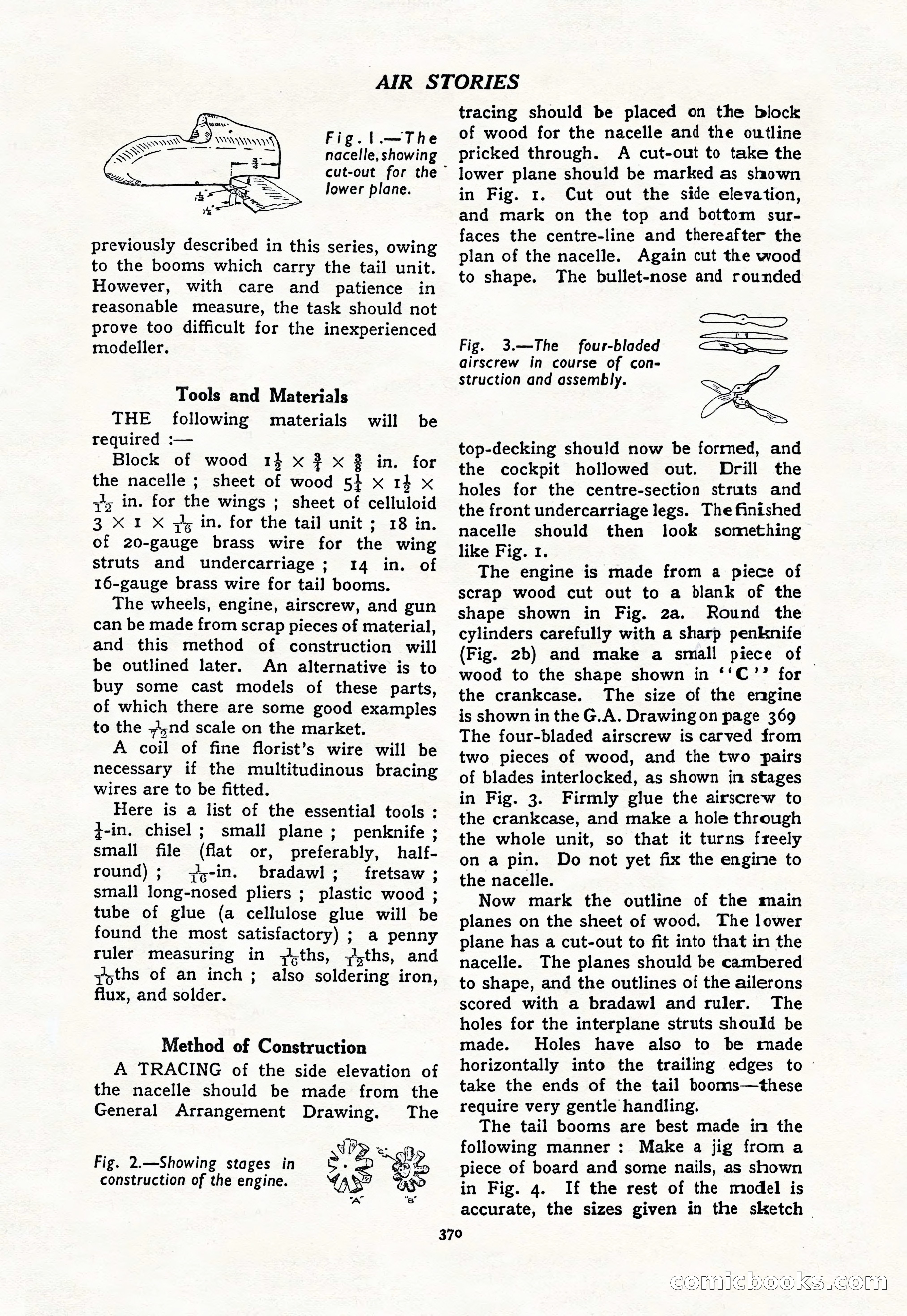
A restored page from Pulp Fiction, 1936. Page through the whole issue in the reader above.
📄 Transcribed text from this page (OCR, searchable)
Machine-transcribed from the original scan — historical spelling and the odd misread are preserved.
AIR STORIES Fig.!.—The nacelle, showing lower plane. previously described in this series, owing to the booms which carry the tail unit. However, with care and patience in reasonable measure, the task should not prove too difficult for the inexperienced modeller. Tools and Materials THE following materials required :— Block of wood 1} x } x 3 in. for the nacelle ; sheet of wood 5} x 14 x zis in. for the wings ; sheet of celluloid 3 X I X zy in. for the tail unit ; 18 in. of 20-gauge brass wire for the wing struts and undercarriage; 14 in. of 16-gauge brass wire for tail booms. The wheels, engine, airscrew, and gun can be made from scrap pieces of material, and this method of construction will be outlined later. An alternative is to buy some cast models of these parts, of which there are some good examples to the .A,nd scale on the market. A coil of fine florist’s wire will be necessary if the multitudinous bracing wires are to be fitted. Here is a list of the essential tools : z-in. chisel ; small plane ; penknife ; small file (flat or, preferably, half- round); ),-in. bradawl; fretsaw ; small long-nosed pliers ; plastic wood ; tube of glue (a cellulose glue will be found the most satisfactory) ; a penny ruler measuring in +iths, ;,ths, and ZYoths of an inch; also soldering iron, flux, and solder. will be Method of Construction A TRACING of the side elevation of the nacelle should be made from the General Arrangement Drawing. The Fig. 2.—Showing stages in e. > dn: construction of the engine. AS - a” “a” cut-out for the tracing should be placed on the block of wood for the nacelle and the outline pricked through. A cut-out to take the lower plane should be marked as shown in Fig. 1. Cut out the side elevation, and mark on the top and bottom sur- faces the centre-line and thereafter the plan of the nacelle. Again cut the wood to shape. The bullet-nose and rounded : SO cee, Fig. 3.—The four-bladed Se Se airscrew in course of con- struction and assembly. top-decking should now be formed, and the cockpit hollowed out. Drill the holes for the centre-section struts and the front undercarriage legs. The finished nacelle should then look something like Fig. 1. The engine is made from a piece of scrap wood cut out to a blank of the shape shown in Fig. 2a. Round the cylinders carefully with a sharp penknife (Fig. 2b) and make a small piece of | wood to the shape shown in ‘‘C’? for the crankcase. The size of the engine is shown in the G.A. Drawing on page 369 The four-bladed airscrew is carved from two pieces of wood, and the two pairs of blades interlocked, as shown in stages in Fig. 3. Firmly glue the airscrew to the crankcase, and make a hole through the whole unit, so that it turns freely on a pin. Do not yet fix the engine to the nacelle. Now mark the outline of the main planes on the sheet of wood. The lower plane has a cut-out to fit into that in the nacelle. The planes should be cambered to shape, and the outlines of the ailerons scored with a bradawl and ruler. The holes for the interplane struts should be made. Holes have also to be made horizontally into the trailing edges to - take the ends of the tail booms—these require very gentle handling. The tail booms are best made in the following manner: Make a jig from a piece of board and some nails, as shown 370 in Fig. 4. If the rest of the model is accurate, the sizes given in the sketch COMnmicoooks.con