
Pulp Fiction, 1929 · page 69 of 95
Air Wonder Stories, August 1929 — page 69: what you’re looking at
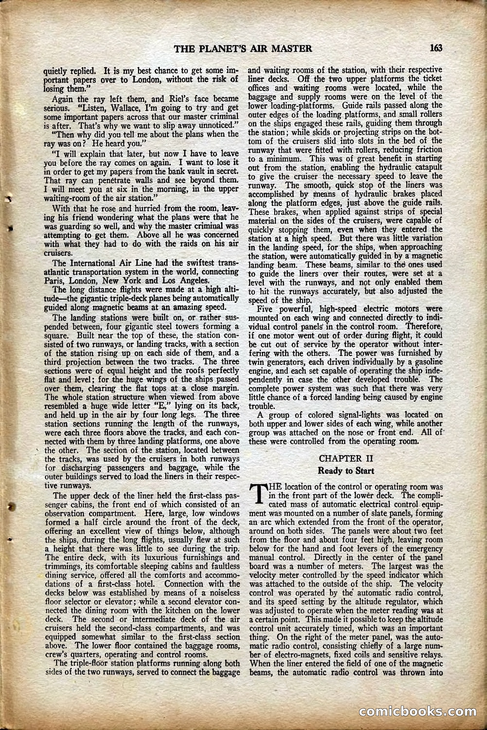
A restored page from Pulp Fiction, 1929. Page through the whole issue in the reader above.
📄 Transcribed text from this page (OCR, searchable)
Machine-transcribed from the original scan — historical spelling and the odd misread are preserved.
THE PLANET'S AIR MASTER quietly replied. It is my best chance to get some im- portant papers over to London, without the risk of losing them.” Again the ray left them, and Riel’s face became serious, “Listen, Wallace, I’m going to try and get some important papers across that our master criminal is.after, That's why we want to slip away unnoticed.” “Then why did you tell me about the plans when the ray was on? He heard you,” “T will explain that later, but now I have to leave you before the ray comes on again. I want to lose it in order to get'my papers from the bank vault in secret. That ray can penetrate walls and see beyond them. TI will meet you at six in the morning, in the upper waiting-room of the air station.” With that he rose and hurried from the room, leav- ing his friend wondering what the plans were that he was guarding so well, and why the master criminal was attempting to get them. Above all he was concerned with what they had to do with the raids on his air cruisers. The International Air Line had the swiftest trans- atlantic transportation system in the world, connecting Paris, London, New York and Los Angeles. The long distance flights were made at a high alti- tude—the gigantic triple-deck planes being automatically guided along magnetic beams at an amazing speed. The landing stations were built on, or rather sus- pended between, four gigantic steel towers forming a square, Built near the top of these, the station con- sisted of two runways, or landing tracks, with a section of the station rising upon each: side of them, and a third projection between the two tracks. The three sections were of equal height and the roofs perfectly flat-and level; for the huge wings of the ships passed over them, clearing the flat tops ata close margin. The whole station structure when viewed from above resembled a- huge wide letter “EK,” lying on its back, and held up in the air by four long legs. The three station sections running the length of the runways, were each three floors above the tracks, and each con- nected with them by three landing platforms, one above the other.. The section of the station, located between the tracks, was used by the cruisers in both runways for discharging passengers and baggage, while the outer buildings served to load the liners in their respec- tive runways. The upper deck of the liner held the first-class pas- senger cabins, the front end of which consisted-of an observation compartment. Here, large, low windows formed a half circle around the front of the deck, offering- an excellent view of things below, although the ships, during the long flights, tisually flew at such a height that there was little to see during the trip. The entire: deck, with its luxurious furnishings and trimmings, its comfortable sleeping cabins and faultless dining service, offered all the comforts and accommo- dations of a first-class hotel. Connection with the decks below was established by means of a noiseless floor selector or elevator; while a second elevator con- nected the dining-room with the kitchen on the lower deck, The second or intermediate deck of the air cruisers held the second-class compartments, and was equipped somewhat similar to the first-class section above. The lower floor contained the baggage rooms, crew’s quarters, operating and control rooms. The triple-floor station platforms running along both sides of the two runways, served to connect the baggage and waiting rooms of the station, with their respective liner decks. Off the two upper platforms the-ticket offices and waiting rooms were located, while the baggage and supply rooms were. on the level of the lower loading-platforms, Guide rails passed along the outer edges of the loading platforms, and small rollers on the ships engaged these rails, guiding them through the:station; while skids or.projecting strips on-the bot- tom. of the cruisers slid into slots in the bed of the tunway that were fitted with rollers, reducing friction to a minimum, This. was of great benefit in starting out from the station, enabling the hydraulic. catapult to give the cruiser the necessary speed to leave the tunway. The smooth, quick stop of the liners was accomplished by means of hydraulic brakes placed along the platform edges, just-above the guide rails. These ‘brakes, when applied against ‘strips of special material on the sides of the cruisers, were capable of quickly stopping them, even when they entered the station at a high speed. But there was little variation in the landing speed, for the ships, when approaching the station, were automatically guided in by a magnetic landing beam. These beams, similar to thé ones used to guide the liners over their routes, were set at a level with the runways, and me only enabled them to. hit-the runways accurately, but also adjusted the speed of the ship. Five powerful, high-speed electric motors were mounted on. each wing and connected directly to indi- vidual. control panels in the control room. Therefore, if one motor went out of order. during flight, it could be cut out of service by the operator without inter- fering with the others. The power was furnished by twin generators, each driven individually by a gasoline engine, and each set capable of. operating the ship inde- pendently in case the other developed trouble. The complete power system. was such that there was very little chance of a forced landing being caused by engine trouble. A group of colored signal-lights was located on both upper and lower sides of each wing, while another group was attached on the nose or front end. All of these were. controlled from the operating room. CHAPTER II Ready to Start HE location of the control-or operating room was in the front part of the lowér deck, The compli- cated mass of automatic electrical control. equip- ment:was mounted.on a number of slate panels, forming an atc which extended from the front of the operator, around on both sides. The panels were about two feet from-the floor and about four feet high, leaving room below for the hand and foot levers of the emergency manual. control. Directly in the center of the panel board was.a number of meters. The largest was the velocity meter controlled by the speed indicator which was attached to the outside of the ship. The velocity control was operated by the automatic radio control, and its speed setting by the altitude regulator, which was adjusted to operate when the-meter reading was at acertain point, This.made it possible to keep the altitude control unit accurately timed, which was an important thing. On the right of the meter-panel, was the auto- tmatic radio control, consisting chiefly of a large num- ber of electro-magnets, fixed coils and sensitive relays. When the liner entered the field of one of the magnetic beams, the automatic radio control was thrown into ——- re =" “=e = 2 in abbiniee bh cd eee oe wt Ahh Dee SP Ce ee ee ee ee