
Pulp Fiction, 1938 · page 84 of 100
Air Stories — page 84: what you’re looking at
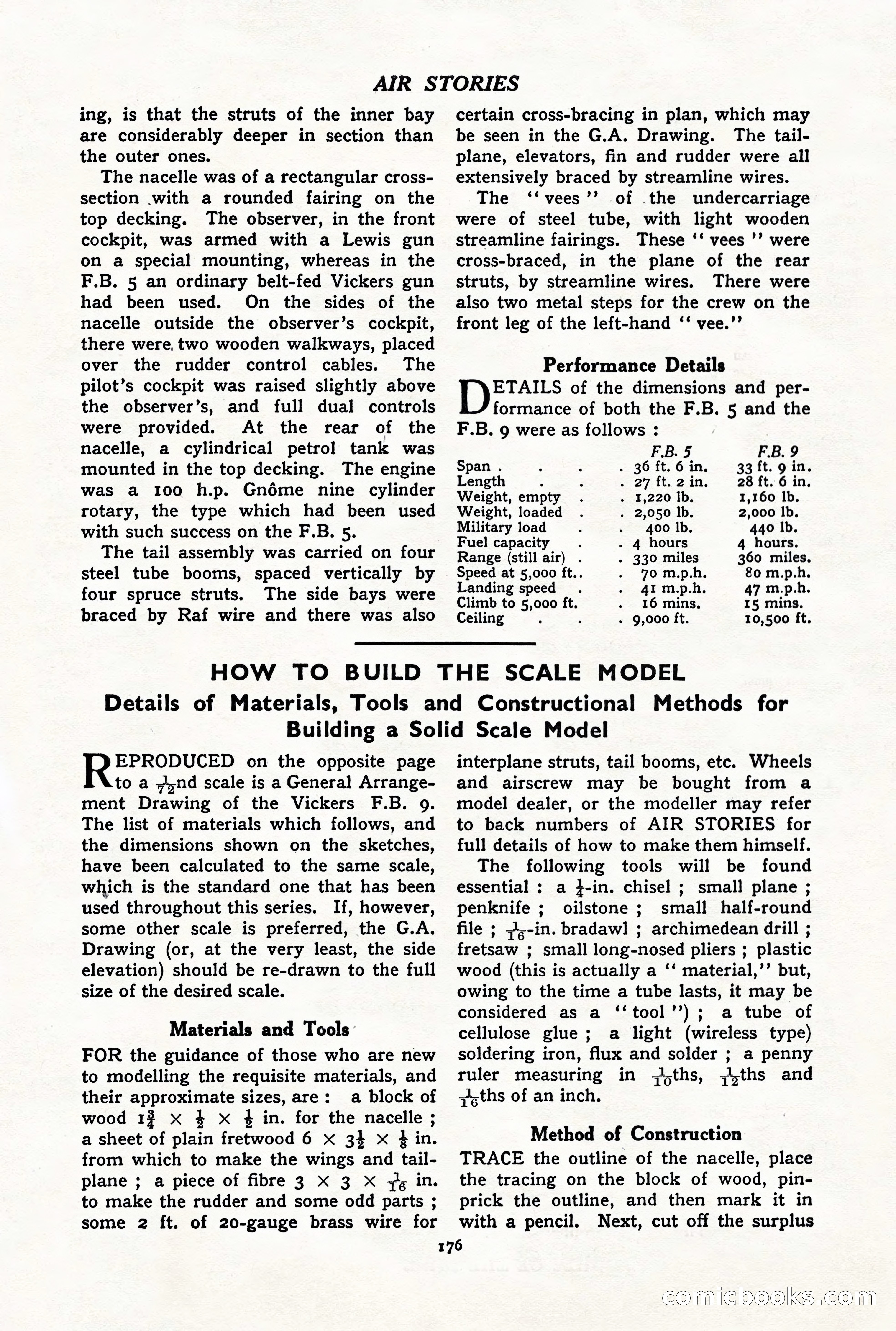
A restored page from Pulp Fiction, 1938. Page through the whole issue in the reader above.
📄 Transcribed text from this page (OCR, searchable)
Machine-transcribed from the original scan — historical spelling and the odd misread are preserved.
AIR STORIES ing, is that the struts of the inner bay are considerably deeper in section than the outer ones. The nacelle was of a rectangular cross- section with a rounded fairing on the top decking. The observer, in the front cockpit, was armed with a Lewis gun on a special mounting, whereas in the F.B. 5 an ordinary belt-fed Vickers gun had been used. On the sides of the nacelle outside the observer’s cockpit, there were, two wooden walkways, placed over the rudder control cables. The pilot’s cockpit was raised slightly above the observer’s, and full dual controls were provided. At the rear of the nacelle, a cylindrical petrol tank was mounted in the top decking. The engine was a 100 h.p. Gnéme nine cylinder rotary, the type which had been used with such success on the F.B. 5. The tail assembly was carried on four steel tube booms, spaced vertically by four spruce struts. The side bays were braced by Raf wire and there was also certain cross-bracing in plan, which may be seen in the G.A. Drawing. The tail- plane, elevators, fin and rudder were all extensively braced by streamline wires. The ‘‘vees’’ of the undercarriage were of steel tube, with light wooden streamline fairings. These ‘‘ vees ’’ were cross-braced, in the plane of the rear struts, by streamline wires. There were also two metal steps for the crew on the front leg of the left-hand ‘‘ vee.’’ Performance Details ETAILS of the dimensions and per- formance of both the F.B. 5 and the F.B. 9 were as follows : F.B. 5 F.B. 9 Span . . 36 ft. 6 in. 33 ft. 9 in. Length : . 27 ft. 2 in. 28 ft. 6 in. Weight, empty . 1,220 lb. 1,160 lb. Weight, loaded . 2,050 lb. 2,000 Ib. Military load 400 lb. 440 Ib. Fuel capacity ; . 4 hours 4 hours. Range (still air) . - 330 miles 360 miles. Speed at 5,000 ft.. 70 m.p.h. 80 m.p.h. Landing speed 41 m.p.h. 47 m.p.h. Climb to 5,000 ft. 16 mins. 15 mins. Ceiling ; ; - 9,000 ft. 10,500 ft. HOW TO BUILD THE SCALE MODEL Details of Materials, Tools and Constructional Methods for Building a Solid Scale Model EPRODUCED on the opposite page to a nd scale is a General Arrange- ment Drawing of the Vickers F.B. 9. The list of materials which follows, and the dimensions shown on the sketches, have been calculated to the same scale, which is the standard one that has been used throughout this series. If, however, some other scale is preferred, the G.A. Drawing (or, at the very least, the side elevation) should be re-drawn to the full size of the desired scale. Materials and Tools FOR the guidance of those who are new to modelling the requisite materials, and their approximate sizes, are: a block of wood 13 x 4 X ¢ in. for the nacelle ; a sheet of plain fretwood 6 xX 34 x 4 in. from which to make the wings and tail- plane ; a piece of fibre 3 X 3 X 7, in. to make the rudder and some odd parts ; some 2 ft. of 20-gauge brass wire for interplane struts, tail booms, etc. Wheels and airscrew may be bought from a model dealer, or the modeller may refer to back numbers of AIR STORIES for full details of how to make them himself. The following tools will be found essential ; a }-in. chisel ; small plane ; penknife ; oilstone ; small half-round file ; =4,-in. bradawl ; archimedean drill ; fretsaw ; small long-nosed pliers ; plastic wood (this is actually a ‘‘ material,’’ but, owing to the time a tube lasts, it may be considered as a ‘‘tool’’); a tube of cellulose glue; a light (wireless type) soldering iron, flux and solder ; a penny ruler measuring in ;,ths, ;,ths and jsths of an inch. Method of Construction TRACE the outline of the nacelle, place the tracing on the block of wood, pin- prick the outline, and then mark it in with a pencil. Next, cut off the surplus 176 COmiclbookk CO